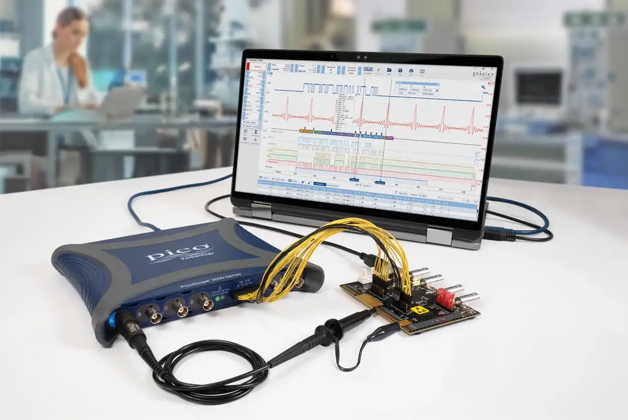
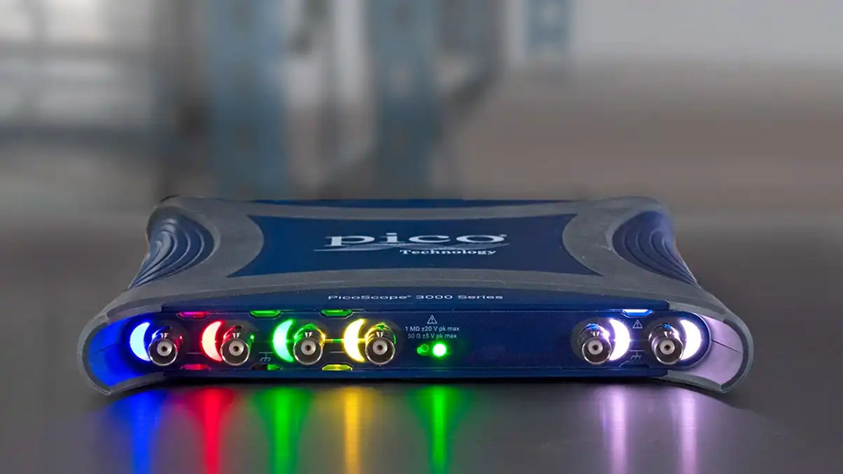
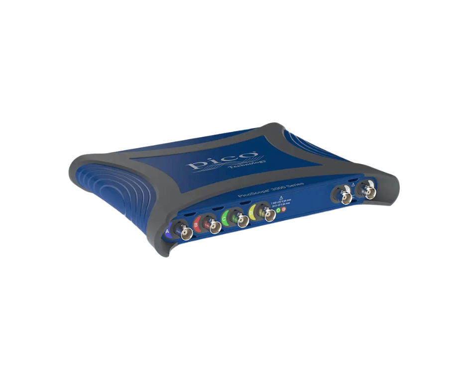
The PicoScope 3000E Series USB Mixed-Signal Oscilloscope is designed for engineers, researchers, technicians, electronics manufacturers and educational laboratories that require high-speed analogue acquisition and time-correlated digital logic analysis in a portable PC-based instrument.
The MSO models combine:
- Four analogue oscilloscope channels
- Sixteen digital logic channels
- 100 MHz to 500 MHz model-dependent bandwidth
- Up to 5 GS/s real-time sampling
- Selectable 8-bit and 10-bit hardware resolution
- Up to 14-bit enhanced resolution
- Up to 2 GS capture memory
- Built-in 20 MHz function generator
- Built-in 14-bit, 200 MS/s arbitrary waveform generator
- More than 40 serial protocol decoders
- PicoScope 7 software
- PicoSDK support
- USB Type-C connectivity and power
The range is suitable for advanced embedded-system design, analogue electronics, power conversion, automotive electronics, communications, research, production testing and educational applications.
PicoScope 3000E MSO Model Range
The current mixed-signal models include:
| Model |
Analogue Bandwidth |
Analogue Channels |
Digital Channels |
| PicoScope 3415E MSO |
100 MHz |
4 |
16 |
| PicoScope 3416E MSO |
200 MHz |
4 |
16 |
| PicoScope 3417E MSO |
350 MHz |
4 |
16 |
| PicoScope 3418E MSO |
500 MHz |
4 |
16 |
All models provide four analogue channels. The MSO versions add 16 digital channels for logic analysis and mixed-signal debugging.
Up to 500 MHz Analogue Bandwidth
The PicoScope 3000E Series offers four bandwidth choices:
- 100 MHz
- 200 MHz
- 350 MHz
- 500 MHz
Typical rise times are:
- 3.5 ns for 100 MHz models
- 1.75 ns for 200 MHz models
- 1.2 ns for 350 MHz models
- 925 ps for 500 MHz models
This range supports applications from general embedded-system testing to higher-speed digital and communication measurements.
Suitable measurements include:
- Microcontroller and FPGA clocks
- PWM and pulse waveforms
- High-speed digital interfaces
- Switching power-supply signals
- Gate-drive waveforms
- Analogue amplifier outputs
- Sensor and actuator signals
- Automotive control systems
- Communication physical layers
- Signal-integrity problems
- Power-rail noise and ripple
- Multi-channel timing relationships
The selected model should match the highest frequency component and rise time that must be measured accurately.
Four Analogue Input Channels
Every PicoScope 3000E model provides four analogue channels.
Four-channel acquisition supports simultaneous analysis of:
- Clock, data, enable and reset signals
- Input and output waveforms
- Voltage and current
- Multiple power rails
- High-side and low-side gate drives
- Converter input and output
- Sensor signal and controller response
- Reference and measured waveforms
- Phase and timing relationships
- Multi-stage start-up sequences
All active analogue channels are sampled simultaneously, helping preserve accurate timing relationships between signals.
Sixteen Digital Logic Channels
PicoScope 3000E MSO models add 16 digital inputs for mixed-signal analysis.
Digital channels can be used for:
- Microcontroller GPIO debugging
- FPGA and CPLD testing
- Parallel bus analysis
- Clock and data timing
- Logic-pattern triggering
- Embedded communication testing
- Analogue and digital signal correlation
- Digital control-system troubleshooting
The channels can be organised into buses, with values displayed in:
- Binary
- Decimal
- Hexadecimal
- Logic-level format
Advanced triggers can combine conditions from both analogue and digital channels.
Up to 5 GS/s Real-Time Sampling
The PicoScope 3000E Series provides up to 5 GS/s real-time sampling.
Sampling performance depends on:
- Hardware resolution
- Number of active analogue channels
- Number of active digital channel groups
- Selected acquisition mode
- Time-base setting
The 5 GS/s headline specification allows detailed capture of fast edges, short pulses and high-frequency waveform content.
High-speed sampling supports analysis of:
- Ringing and overshoot
- Narrow glitches
- Fast clock edges
- Switching transients
- Timing variation
- Communication waveform quality
- Pulse distortion
- Intermittent signal abnormalities
The final per-channel sample rate should be checked for the required active-channel configuration.
Selectable 8-Bit and 10-Bit Resolution
The PicoScope 3000E Series supports selectable hardware resolution:
- 8-bit mode for maximum acquisition speed and bandwidth flexibility
- 10-bit mode for improved vertical detail and lower noise
Software-based enhanced resolution can add up to four additional bits, providing up to 14-bit enhanced resolution under suitable acquisition conditions.
The 10-bit mode provides four times the vertical quantisation levels of an 8-bit oscilloscope.
It is useful for:
- Power-supply ripple measurements
- Analogue signal analysis
- Sensor testing
- Low-noise circuit development
- Power-integrity measurements
- Amplifier evaluation
- Small signals riding on DC levels
The selected resolution may affect the available bandwidth, sampling rate and memory allocation.
Up to 2 GS Capture Memory
The PicoScope 3000E Series provides ultra-deep acquisition memory.
In 8-bit mode, available capture memory is:
- 2 GS with one active channel
- 1 GS per channel with two active channels
- 512 MS per channel with three or four active channels
- 256 MS per active channel or digital port when more than four acquisition resources are enabled
In 10-bit mode, memory allocation is:
- 1 GS with one active channel
- 512 MS per channel with two active channels
- 256 MS per channel with three or four active channels
- 128 MS per active acquisition resource when more than four are enabled
Deep memory helps maintain high sampling rates during long acquisitions.
It is useful for:
- Long serial communication captures
- Power-supply start-up analysis
- Embedded-system timing sequences
- Long PWM records
- Intermittent fault investigation
- Packet-based communication testing
- Production monitoring
- Detailed waveform zooming
Segmented Memory and Rapid Triggering
The acquisition memory can be divided into segments so that selected events are stored separately without filling memory with inactive periods.
PicoScope 7 supports up to:
PicoSDK supports up to:
Rapid trigger mode can acquire a new waveform approximately every 700 ns, giving an effective capture rate of up to 2 million waveforms per second until the waveform buffer is full.
Segmented acquisition is useful for:
- Communication packets
- Laser pulses
- Switching events
- Injector or ignition pulses
- Intermittent glitches
- Repetitive production tests
- Rare trigger conditions
Waveform Buffer and Navigator
PicoScope 7 stores the most recent 40,000 oscilloscope or spectrum waveforms in a circular buffer.
Users can:
- Review earlier waveforms
- Search for mask violations
- Filter failed measurements
- Compare normal and abnormal captures
- Apply serial decoding to captured buffers
- Run DeepMeasure analysis
- Navigate through rapid-trigger acquisitions
This helps engineers investigate transient events that may disappear before acquisition is stopped manually.
Built-In 20 MHz Function Generator
All PicoScope 3000E models include a built-in function generator with a frequency range from approximately:
The generator supports:
- Standard waveform output
- Adjustable frequency
- Adjustable output level
- DC offset control
- Frequency sweeps
- Triggered burst operation
- Gated waveform output
Typical applications include:
- Amplifier testing
- Filter evaluation
- Circuit stimulus generation
- Sensor simulation
- Clock generation
- Frequency-response testing
- Educational experiments
- Production validation
The generator output is available through a dedicated front-panel BNC.
Built-In 14-Bit Arbitrary Waveform Generator
Every PicoScope 3000E model also includes a:
- 14-bit AWG
- 200 MS/s update rate
Arbitrary waveforms can be:
- Created in the waveform editor
- Imported from spreadsheets
- Loaded from CSV files
- Derived from captured oscilloscope signals
- Edited for application-specific testing
The AWG allows users to reproduce real-world or custom test signals without requiring a separate arbitrary waveform generator.
More Than 40 Serial Protocol Decoders
PicoScope 7 includes more than 40 serial protocol decoders as standard, without separate paid decoding licences.
Supported protocols include:
- I²C
- SPI
- RS232/UART
- CAN
- CAN FD
- CAN J1939
- CAN XL
- LIN
- FlexRay
- I²S
- USB 1.0 and 1.1
- Ethernet
- 10BASE-T1S
- 100BASE-TX
- BroadR-Reach
- ARINC 429
- MIL-STD-1553
- MODBUS ASCII
- MODBUS RTU
- PMBus
- SMBus
- SENT
- PSI5
- Manchester
- Differential Manchester
- Parallel bus
Up to 20 channels of serial data can be decoded, depending on available analogue and digital inputs.
Decoded information can be displayed:
- Alongside the waveform
- In an event table
- In numerical format
- Across multiple waveform buffers
Advanced Digital Triggering
PicoScope uses digitised waveform data for triggering rather than relying only on conventional analogue trigger comparators.
Available trigger types include:
- Edge
- Pulse width
- Window
- Runt pulse
- Dropout
- Logic
- Level
- Interval
- Digital pattern
- Serial protocol conditions
- Combined analogue and digital triggers
Digital triggering provides precise threshold control and supports stable triggering on small signals at full bandwidth.
DeepMeasure Analysis
DeepMeasure automatically calculates waveform parameters for individual cycles within long acquisitions.
It can analyse up to approximately one million cycles per triggered acquisition and provide results such as:
- Frequency
- Period
- Pulse width
- Rise time
- Fall time
- Duty cycle
- Maximum and minimum voltage
- Amplitude
- Timing variation
Results can be:
- Sorted
- Filtered
- Correlated with the waveform
- Exported for additional analysis
This is useful for identifying occasional timing or amplitude abnormalities within long records.
FFT Spectrum Analysis
PicoScope 7 can display oscilloscope and spectrum views together.
Spectrum-analysis functions include:
- FFT frequency-domain display
- Peak hold
- Averaging
- Multiple window functions
- Logarithmic scaling
- Harmonic analysis
- Noise measurement
- Frequency markers
- Spectrum masks
The AWG and spectrum analyser can also be used together for swept frequency-response testing of filters and amplifiers.
Mask Limit Testing
Mask testing compares live or stored waveforms against a known-good reference envelope.
Users can:
- Automatically generate a mask
- Count passed and failed waveforms
- Search the waveform buffer for violations
- Save masks for later use
- Import or export masks
- Trigger automated actions after a failure
Mask testing is suitable for:
- Production-line validation
- Repetitive quality checks
- Signal-stability monitoring
- Component comparison
- Intermittent fault detection
- Long-duration soak testing
Automated Actions
PicoScope 7 can perform automated actions when selected events occur.
Events can include:
- Trigger conditions
- Mask failures
- Measurement-limit failures
- Waveform buffer full
Available actions include:
- Stop acquisition
- Save waveforms
- Save screenshots
- Play an alert sound
- Trigger the AWG
- Run an external program
This supports unattended testing, production validation and long-duration monitoring.
PicoScope 7 Software
PicoScope 7 is available for:
The software includes:
- Oscilloscope views
- Spectrum views
- Serial decoding
- Automatic measurements
- Waveform mathematics
- DeepMeasure
- Mask testing
- Measurement limits
- Reference waveforms
- Custom probes
- Actions
- Segmented memory
- Waveform buffer navigation
Software updates and new analysis functions are provided without recurring licence charges.
PicoSDK and Automated Test Integration
PicoSDK allows engineers to build custom acquisition and automated test applications.
It supports integration with:
- C
- C++
- C#
- Python
- MATLAB
- LabVIEW
- Custom OEM applications
Typical uses include:
- Production testing
- Automated validation
- Research systems
- Data logging
- Custom user interfaces
- OEM integration
- Remote monitoring
Continuous gap-free streaming to a host computer can exceed 300 MS/s under suitable system conditions.
USB Type-C Power and Connectivity
The PicoScope 3000E Series uses a SuperSpeed USB Type-C connection for:
- Instrument power
- Waveform transfer
- Remote control
- Software communication
A USB-A to USB-C cable and external power option support computers that cannot supply the full required power through their USB port.
Other hardware features include:
- AUX input and output
- External trigger capability
- AWG output
- Status and trigger indicators
- Channel-colour indicators
- Kensington security slot
Applications
The PicoScope 3000E Series MSO is suitable for:
- Embedded-system development
- Microcontroller debugging
- FPGA and CPLD testing
- Mixed-signal circuit analysis
- High-speed digital design
- Power electronics testing
- Switching power-supply analysis
- Serial protocol debugging
- Automotive electronics
- CAN and LIN analysis
- Communications testing
- Signal-integrity troubleshooting
- Analogue circuit development
- Semiconductor evaluation
- Research and development
- Production-line testing
- Engineering education
- Portable field measurements
- OEM and automated test integration